电子镇流器、现代LED照明、节能灯或电源适配器在开关时通常会产生高启动电流,其值可达额定电流的250倍。为此,ComatReleco提供专用于高启动电流的继电器:
- CHI14 / CHI34:零交叉开关,启动电流高达 800A,持续时间 800us
- C7-W10:带钨预热触点,启动电流高达 500A,持续时间 2.5ms
- C10-A15:带银氧化锡触点,启动电流高达 120A,持续时间 20ms
- CIM14:带零交叉控制的定时继电器,最大启动电流800A,持续时间800微秒
电阻和电容器的串联电路在断开过程中,使电流以衰减的振荡方式逐渐消失。在通电过程中,电阻阻止电容器的全部电荷通过开关触点放电。通过RC电路实现的保护电路非常适合交流电压。此外,还能实现立即断开限制。
A reliable three pole LED step switch can be implemented with the CHI34/UC24-240V together with the CIM1/UC24-240V. The CIM1 manages the step logic. The CHI34 is designed for modern LED systems and ensures stable switching of the lighting.
线圈电压?
- 交流和直流线圈电压可在目录中找到。如果您无法找到适合您应用的线圈电压,ComatReleco的技术支持团队可为您提供进一步帮助。
需要切换的负载?
- 负载类型?
- 要切换的负载是欧姆负载吗?是电感负载吗?是电容负载吗?这是选择继电器/保护开关时需要了解的一个非常重要的因素。
- 交流电?直流电?
- 要切换的负载是交流电还是直流电?电压是多少?
切换频率?
- 继电器每天、每小时、每分钟甚至每秒需要切换多少次?如果开关循环次数较多,建议使用半导体继电器,因为它没有机械触点,因此使用寿命几乎无限。
环境?
- 这包括继电器/接触器安装的环境温度。还包括环境信息:是否多尘?是否会进入水分?是否有腐蚀性气体?还有其他值得注意的因素吗?
切换小信号时,需要注意什么?
- 如果需要切换毫安级信号,则必须选择具有相应最小负载的合适继电器。带镀金触点的继电器非常适合。金具有很好的导电性,因此可以切换小信号。但金在电流过高时容易熔化触点。ComatReleco 还提供双金触点继电器。这些双触点可提高控制和信号电路的开关安全性。
- 除了机械继电器外,还可以使用半导体继电器。ComatReleco 的 CSS 系列可可靠地切换 1mA(直流)和 35mA(交流)以上的电流。
自由轮二极管用于在切断感应直流负载时防止过电压。为此,二极管与感应直流负载并联连接,使其在反向电压作用下导通。在切断电源电压后,线圈的自感会使电流首先继续沿原方向流动。如果没有自由轮转二极管,就会产生电压尖峰,该尖峰会叠加到工作电压上,从而损坏或破坏开关电路。然而,使用自由轮转二极管可将电压尖峰限制在二极管的正向电压(硅二极管约为 0.7 V)范围内。这不仅能有效保护电子元件,还能有效防止开关触点因过电压而损坏。
The 3- to 4-digit code on the product is the so-called LOT code. It is a batch code that allows the product to be clearly assigned to a specific production batch.
The LOT code is printed directly on the product and is used for traceability, quality control and for support and service requests.
Depending on the product type, the LOT code is printed in different locations:
- On plug-in relays, the LOT code is printed on the top of the product.
- On other products, the LOT code is part of the side marking or printed on the rear side.
- On products for DIN rail mounting, the LOT code is usually printed on the rear side.
The manual actuator of our pluggable relays is colour-coded according to the coil voltage. This makes it easy to recognise the correct voltage type and avoids confusion.
| red | 230 V AC (50 Hz & 60 Hz) |
| dark red | other AC voltages |
| blue | 24 V DC |
| dark blue | other DC voltages |
| grey | suitable for AC and DC voltages (universal current "UC") |
| orange | push only This manual actuator cannot be locked, but will override the coil and actuate the contacts when pressed. |
| black | Dummy button. This manual actuator can be used if the relay must not be operated manually. The regular actuator can be replaced with this black dummy button. This prevents any further manual actuation. |
First, remove the existing manual actuator by pulling it upwards with a slotted screwdriver. A size 0 or 00 slotted screwdriver is recommended. Once removed, you can insert the new actuator, for example a dummy button or a push-only button.

- 适用于频繁且快速的开关操作
- 长寿命,因采用无磨损的半导体输出
- 无弹跳,因无活动触点
- 不产生电磁干扰
- 抗机械影响,如冲击和振动
C2和C3型工业继电器可通过时间模块改造成时间继电器。当获得具有所需时间功能的时间模块后,将其插入继电器与底座之间。
底座C12B0和CS-155(S5-M)配备有模块插槽,专用于时间模块/监控模块。因此,除了底座和工业继电器外,只需额外添加一个可插拔的时间模块即可。
几乎所有时间继电器的设置过程都相同。首先,通过电位器选择一个功能。每个字母(A、E、W、K 等)代表一个特定功能,该功能在继电器侧或随附说明书中有所描述。
接下来,选择时间范围,所选范围始终为最大值。最后,使用最后一个电位器进行时间微调。例如,要设置 30 秒的延迟关闭,操作如下:
功能:A
时间范围:60 秒
微调:在 0-6 的刻度上,将电位器调至 3(6= 60 秒,3 = 30 秒,1 = 10 秒)。
E – On delay
The function provides a delayed switching ON of the output.
When S switches ON, the time t starts.
After t expires, the output R switches ON.
If S switches OFF before t ends, R stays OFF.
A – Off delay
The function provides a delayed switching OFF of the output.
When S switches ON, the output R switches ON immediately.
When S switches OFF, the time t starts.
After t expires, the output R switches OFF.
F – On and off delay
The function provides a delayed switching ON and a delayed switching OFF of the output.
When S switches ON, the on delay t₁ starts.
After t₁ expires, the output R switches ON.
When S switches OFF, the off delay t₂ starts.
After t₂ expires, the output R switches OFF.

W – One shot leading edge
The function provides a fixed output pulse on the leading edge of the trigger.
When S switches ON, the output R switches ON for time t.
After t expires, R switches OFF, independent of S.
When S switches OFF, R switches OFF.
N – One shot trailing edge
The function provides a fixed output pulse on the trailing edge of the trigger.
When S switches ON, R does not change.
When S switches OFF, the output R switches ON for t.
After t expires, R switches OFF.
Q – One shot leading and trailing edge
The function provides fixed output pulses on both the leading and trailing edges of the trigger.
When S switches ON, the output R switches ON for t1.
After t1 expires, R switches OFF.
When S switches OFF, the output R switches ON again for t2.
After t2 expires, R switches OFF.

K – Pulse shaping
The function provides a fixed output pulse independent of the input duration.
When S switches ON (pulse or continuous), the output R switches ON for t.
During t, S has no influence on R.
After t expires, R switches OFF.
L – Pulse shaping, retrigger
The function provides a fixed output pulse that restarts when retriggered.
When S switches ON, the output R switches ON for t.
If S triggers again during t, the time t restarts from zero.
After the final t expires, R switches OFF.
M – Puls shaping
The function provides a fixed output pulse after S switches OFF.
When S switches ON, R remains OFF.
When S switches OFF, the output R switches ON for t.
After t expires, R switches OFF.

B – Indicator, pulse start
The function provides periodic ON and OFF switching starting with an ON pulse.
When S switches ON, the output R switches ON for time t, then switches OFF for time t.
R switches ON and OFF periodically until S switches OFF. R switches OFF with S.
B1 – Indicator, pulse start, trailing pulse
The function provides periodic ON and OFF switching starting with an ON pulse and ending with a trailing pulse.
the output R switches ON for time t, then switches OFF for time t.
R switches ON and OFF periodically until S switches OFF.
When S switches OFF, the output R switches ON once more for t, then R switches OFF.
B2 – Indicator, interval start
The function provides periodic ON and OFF switching starting with an OFF interval.
When S switches ON, the output R remains OFF for t, then R switches ON for time t.
R switches ON and OFF periodically until S switches OFF. R switches OFF with S.

G – On delay single shot
The function provides an output pulse after a delay.
When S switches ON, the delay t₁ starts.
After t₁ expires, the output R switches ON for t₂.
After t₂ expires, R switches OFF.
During t₂, S has no influence on R.
H – On delay single shot
When S switches ON, the delay t₁ starts.
After t₁ expires, the output R switches ON for t₂.
After t₂ expires, R switches OFF.
When S switches OFF, R switches OFF

I – Repeat cycle timer, pulse start
The function provides periodic ON and OFF switching starting with an ON pulse.
When S switches ON, the output R switches ON for t₁.
After t₁ expires, R switches OFF for t₂.
Afterwards R switches ON and OFF periodically according to t₁ and t₂.
When S switches OFF, R switches OFF.
P – Repeat cycle timer, interval start
The function provides periodic ON and OFF switching starting with an OFF interval.
When S switches ON, the delay t₁ starts, and R remains OFF for t₁.
After t₁ expires, the output R switches ON for t₂.
Afterwards R switches ON and OFF periodically according to t₁ and t₂.
When S switches OFF, R switches OFF.

Y - Star–delta timer
The function provides automatic switching from star operation to delta operation.
When S switches ON, the time t starts, and the star output R switches ON.
After t expires, the star output switches OFF and the delta output switches ON.
When S switches OFF, both outputs switch OFF.
S - Step-on / Step-off switch
The function provides stepwise switching with each activation of the trigger.
Each time S switches, the output R changes state for time t.
The trigger has no time-dependent influence.
LS - Step-switching (staircase lighting timer)
The function provides timed activation with optional stop and reset control.
When S is triggered, the time t starts, and the output R switches ON.
When S is triggered again, the time t stops and R switches OFF.
WhenS is triggered again, the time t resets and starts again immediately.
When t expires, the output R switches OFF.

U – Pulse sequence monitoring
The function provides monitoring of pulse separation and triggers an alarm if pulses are too close together. If the separation becomes smaller than the set time tP, an alarm output is activated after an additional delay tV.
The monitoring starts with S1 or S2.
If the pulse separation of P is smaller than tP, an alarm output is activated after the alarm delay tV.
If the pulse separation is larger than tP, no alarm is triggered.
The start‑up behaviour depends on the selected input S1 (Monitoring begins immediately with the first pulse. There is no suppression of alarm monitoring during start‑up.) or S2 (Monitoring begins after the short‑out time tA to prevent false alarms during system start-up)
V – Pulse sequence monitoring
The function provides monitoring of pulse separation and triggers an alarm if pulses are too far apart.
The monitoring starts with S1 or S2.
If the pulse separation of P is larger than tP, an alarm output is activated after the alarm delay tV.
If the pulse separation is smaller than tP, no alarm is triggered.
The start‑up behaviour depends on the selected input S1 (without start‑up short‑out tA) or S2 (with start‑up short‑out tA).

How can I prevent re‑activation for a defined time after switch‑off?
A re‑activation lockout ensures that a load cannot be switched on again for a defined time after being switched off, even if further impulses are present. Typical applications include device protection, limiting switching frequency or enforcing minimum off‑times. This function can be implemented easily using two time relays, without any special functions.
Example with 2× CIM1/UC24–240 V
Requirement
- A pulse switches the load on.
- The load must remain switched on for 15 min.
- After that, the input must be locked for 2 h.
Time relay settings
Relay 1 (R1): CIM1/UC24–240 V
Function: Off‑delay (A)
Time: 15 min
Relay 2 (R2): CIM1/UC24–240 V
Function: Off‑pulse (N)
Time: 2 h
Operation
When time relay R1 receives a pulse at input B1, its contact 15/18 closes and starts the off‑delay (A).
The load is switched on and remains active for 15 min.
At the same time, a continuous signal is applied to input B1 of the second time relay R2 via the closed contact of R1.
After the 15 min have elapsed, contact 15/18 of R1 opens again.
This falling edge triggers the off‑pulse (N) function on R2.
The normally closed contact of R2 interrupts the supply of R1 for 2 h.
During this time, R1 is blocked and cannot switch again.
Incoming impulses have no effect.
After the 2 h have elapsed, the contact of R2 closes again.
R1 is released and the system is ready for the next cycle.


A latching relay is a bistable relay that retains its switching state even if the supply voltage is interrupted. This means that the last selected switching position - whether switched on or off - remains reliably stored until the relay is deliberately switched over.
A latching relay is used wherever the switching status must be retained after a power failure or interruption. This means that installations or systems can continue to operate safely and stably after an interruption without having to reset the status.
The most important advantages include high energy efficiency and operational reliability. Energy is only required during the changeover, but not to maintain the status. At the same time, the ability to maintain the switching state even in the event of a loss of voltage provides additional reliability and protection against unwanted changes in operation.
A remanence relay works through magnetic remanence: when the relay is switched, residual magnetism remains in the magnetic core, which keeps the armature in its position even if the supply voltage is switched off. The switching state is therefore stored stably until a new control signal generates an opposite magnetic field that compensates for the existing residual magnetism. Only then is the relay deliberately switched into the new state. In this way, it only requires energy during the switching process and combines high efficiency with operational reliability.
当保持继电器两个控制输入同时接通时,A1(ON)始终优先于A3(OFF)。
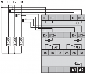
电压、电流、频率、有功功率、视在功率、功率因数、相位角(Delta Phi)。
在设备数据表和随附说明书中,您可以找到菜单操作说明等相关信息。
同时按下两个方向键即可进入菜单。进入设置后,系统将自动引导您完成菜单操作。
为了测量大于5A的电流,需要使用次级侧额定电流为5A的电流互感器。这样就可以测量高电流,但需要在设置中调整“缩放因子”。
这可能是由于电路中存在微小残余电压,该电压足以使继电器线圈保持通电状态。仅需0.1倍的额定电压即可使线圈保持通电!对于230VAC的线圈,继电器仅在电压降至<23VAC时才会断开!
导线/多股线过长往往会产生感应电压,导致继电器无法断开。ComatReleco为此开发了CEM01干扰抑制器。该干扰抑制器与线圈并联连接,可补偿导线的残余电流。这样,继电器就能正常断开了。
If a relay or contactor comes into contact with fresh or dirty water, reliable operation is no longer guaranteed. Corrosion of contacts and conductors can occur, especially in combination with dirt or salts. Even if the component appears to work again after drying, there is still a risk of hidden damage.
A relay affected by moisture can fail unpredictably, get stuck in a switching position or transmit faulty signals. There is also a risk of internal short circuits or arcing, especially in high-current applications. Such failures not only jeopardise operational safety, but can also result in considerable consequential damage.
For this reason, it is always the better and safer decision to replace an affected relay or contactor. The costs for a new device are comparatively low, while the potential costs due to failures or consequential damage can exceed the acquisition costs many times over. This is the only way to ensure the usual quality and reliability in the long term.